DIY Chip-Off Firmware Extraction with a RasPi
In this post I will show you how to read the contents of a simple SPI flash chip using a bare-metal connection to a Raspberry Pi (Model 3 B+).
This post builds on some topics already covered in detail in the fsapi-tools - Firmware Analysis - I recommend reading that afterwards for deeper firmware analysis context.
Below I walk through the steps required to prepare a Raspberry Pi and extract the full contents of an SPI flash chip. Required items:
- A working Raspberry Pi (you will need 6 GPIO pins),
- A soldering iron (or an equivalent desoldering tool),
- The datasheet for the target flash chip,
- Time and patience.
1. Target Selection
For a side project (see fsapi-tools - README), I was curious whether it would be possible to read the flash chip located on the Chorus 3 PCB to gain additional insights into the firmware structure.
After locating the chip on the PCB I looked up its datasheet. The chip is a simple Adesto SPI flash; the datasheet is available freely (adesto - AT45DB321E).
 ® 2019 Adesto Technologies. All rights reserved
With the datasheet in hand we can prepare the chip and wire it to the Raspberry Pi.
2. Chip Preparation
Caution: Removing components from a PCB can permanently damage either the board or the component. Understand the desoldering process before proceeding and consider practising on scrap hardware.
Steps:
- Desolder and remove the flash chip from the PCB (desoldering iron, hot air, or an appropriate programmer socket).
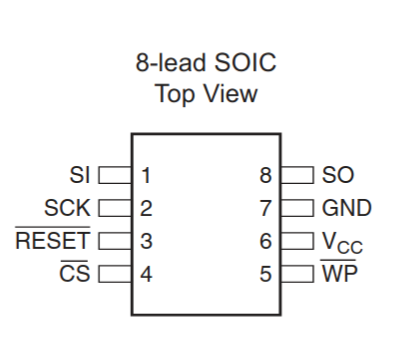
- Solder thin wires to the chip’s pins following the datasheet pinout.
- Connect those wires to the Raspberry Pi GPIO pins.
A useful reference wiring diagram can be found in the splasher - Pinout repository — verify and adapt wiring to the exact pin mapping in your chip’s datasheet.
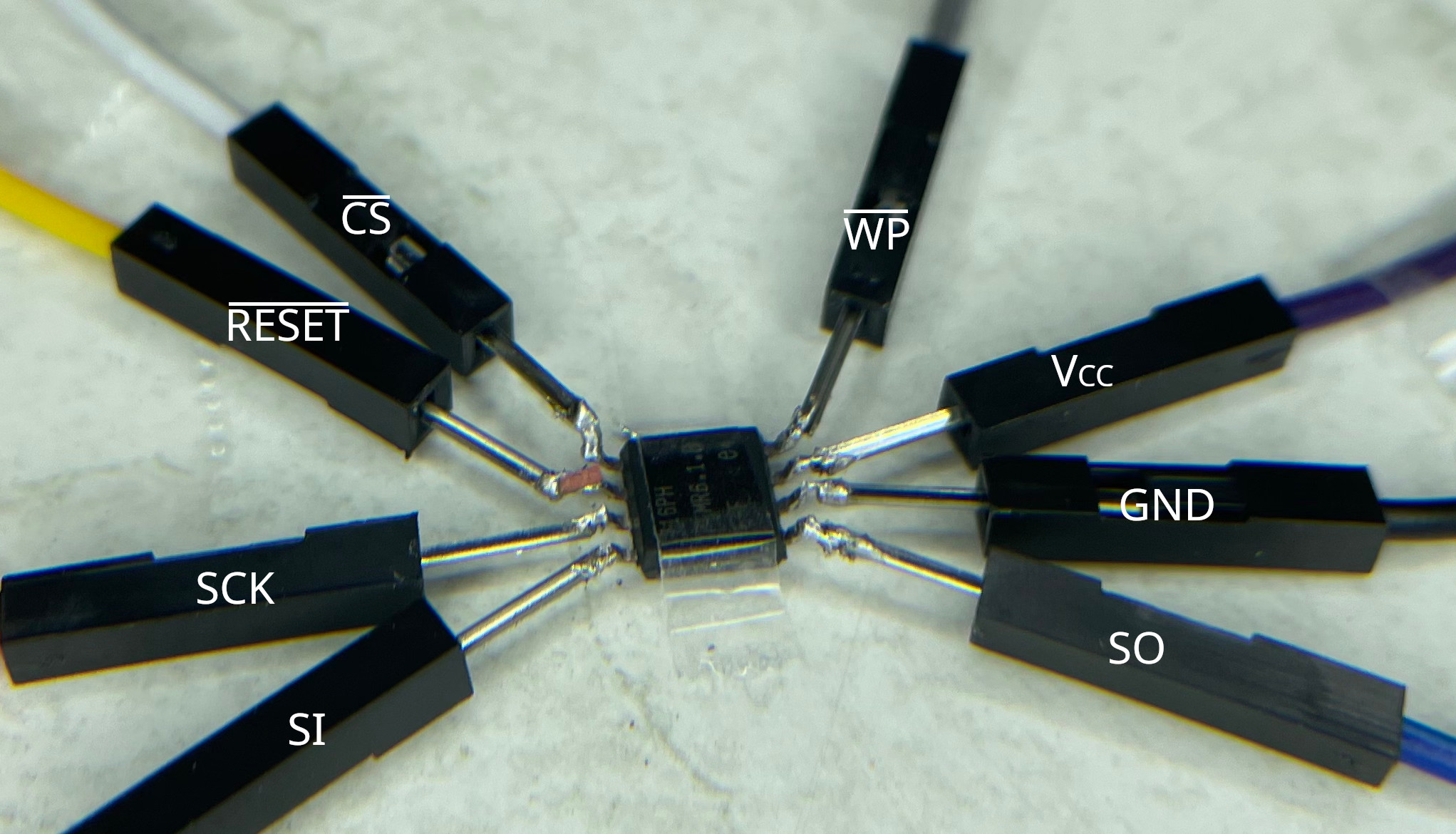 Manually wiring a chip can be challenging. This image shows why universal programmers are often preferred. The chip is shown upside down.
At the time of these experiments my only tool was a soldering iron. Please forgive my (de-)soldering technique — I’m learning by doing.
My setup on the python side looked like this:
1
2
3
4
5
6
7
8
9
10
11
12
13
GPIO.setmode(GPIO.BOARD)

# Force SPI to use specific pins
io_SCLK = 3
io_MISO = 5
io_MOSI = 7
io_HOLD = 11 # equivalent to io_RESET
io_CS   = 13
io_WP   = 15

# setup input/output pins
GPIO.setup([io_SCLK, io_MOSI, io_HOLD, io_CS, io_WP], GPIO.OUT)
GPIO.setup(io_MISO, GPIO.IN)
3. Chip Reader
A professional chip reader is the usual tool for extracting flash contents. As this post demonstrates a DIY approach using the Raspberry Pi’s GPIO, I’ll use a Python script.
I use the RPi.GPIO Python library for direct GPIO control. The goal is to implement the minimal SPI-like signalling needed to talk to the chip (manually toggling CLK, MOSI, MISO, and CS).
3.1 Reading Diagrams
Start by verifying wiring and protocol by reading device manufacturer and device IDs. The datasheet documents the serial commands for this.
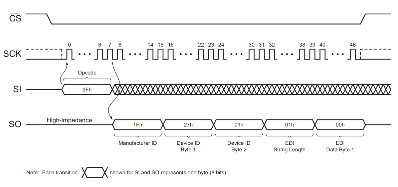 Reading Manufacturer and Device ID, ® 2019 Adesto Technologies. All rights reserved
A simple sequence for reading the manufacturer ID is:
1
2
3
4
5
6
7
8
9
10
11
# 1. Pull CS low to initilaise the SPI interface
GPIO.output(io_CS, GPIO.LOW)
# 2. Write byte and move clock cycle to prepare
#    to receive  manufacturer ID
tx_byte(0x0F)  # <-- we'll see how to do that later on
# 3. simulated clock cycle
clk()
# 4. receive five bytes
data = [rx_byte() for _ in range(5)]
# 5. Deasserting the CS pin will terminate the operation
GPIO.output(io_CS, GPIO.HIGH)
3.2 Implementing basic Actions
The basic primitives we want to implement are:
op_init(): initializing a single operation (step 1: Pull CS low to initilaise the SPI interface)tx_byte(): (step 2.) write byte and move clock cycleclk(): move clock cyclerx_byte(): read one byte and move clock cycleop_finish(): finish the operation by deasserting the CS pin
op_init and op_finish are straightforward: they assert or deassert CS. A clock cycle is a transition on the CLK pin; for a simple implementation:
1
2
3
4
def clk() -> None:
    # one simulated clock cycle
    GPIO.output(io_SCLK, GPIO.HIGH)
    GPIO.output(io_SCLK, GPIO.LOW)
Transmit and receive one byte at a time (MSB first):
1
2
3
4
5
6
7
8
9
10
11
12
13
14
15
16
17
def tx_byte(value: int) -> None:
    # TX Bits, data clocked in on the rising edge of CLK, MSBFirst
    for bit_idx in range(7, 0, -1):
        GPIO.output(io_MOSI, bool((value >> bit_idx) & 0x01))
        clk()

# same formula to read a byte
def rx_byte() -> int:
    value: int = 0
    for _ in range(8):
        # shift existing data to the left
        value <<= 1
        # read one bit and add it to the value
        i = GPIO.input(io_MISO)
        value |= int(i)
        clk()
    return value
Note: The code above assumes MSB-first ordering and a clock/phase convention where the device samples MOSI on the corresponding edge. Consult the datasheet for precise timing and clock phase/polarity requirements.
4. Putting it all together
If wiring and code are correct, reading the device ID should produce sensible manufacturer and device codes. Example output:
1
2
3
4
5
6
7
8
root@raspberrypi:~ # python3 spi_read_deviceid.py
Manufacturer-ID     : 31 (0b11111)
Device-ID
  - Family Code     : 1 (0b1)
  - Density Code    : 7 (0b111)
  - Sub Code        : 0 (0b0)
  - Product Variant : 1 (0b1)
EDI                 : 1 (0b1)
Reading the entire flash depends on chip size; a full dump may take several minutes with a naïve bit-banged implementation. The educational script linked below trades performance for clarity.
- Script reference: spi_read_deviceid.py
Running a script to read the first 1024 bytes produces a file dump.spi.bin in the current directory:
1
2
3
4
root@raspberrypi:~ # sudo python3 spi_read_flash.py
-- snipped --

Reading flash... ━━━━━━━━━━━━━━━━━━━━━━━━━━━━━━━━━━━━━━━━   1% 0:22:56
If the resulting dump is full of 0xFF bytes, that usually indicates a problem: common causes are missing or incorrect clock signalling, incorrect CS handling, or incorrect wiring.
1
2
3
4
5
6
7
8
9
10
11
12
13
00000000: 0055 aa01 1000 0000 00a8 0a00 0000 8f41  .U.............A
00000010: 2510 2002 0080 2302 2201 01c6 7cff 0722  %. ...#."...|.."
00000020: 2201 01b6 0000 0040 8009 2002 2200 01b6  "......@.. ."...
00000030: e5ff 1f22 42c6 18b6 3500 0002 0000 0002  ..."B...5.......
00000040: 22e1 2007 2200 01b6 0c00 0002 22df 2007  ". .".......". .
00000050: 2200 01b6 22e5 2007 2200 01b6 0c00 0002  "...". .".......
00000060: 0500 2403 6209 20ac 0000 0000 0000 0000  ..$.b. .........
00000070: 0000 0000 0000 0000 0000 0000 0000 0000  ................
00000080: 0000 0000 0000 0000 0000 0000 8000 69fc  ..............i.
00000090: 0000 0000 0000 0000 0000 0000 0000 0000  ................
000000a0: 0000 0000 0000 0000 0000 0000 0000 0000  ................
000000b0: 0000 0000 0000 0000 0000 0000 0000 0000  ................
000000c0: 0000 0000 0000 0000 0000 0000 0000 0000  ................
A quick analysis of the flash dump revealed the web server’s files, along with the compressed core of the firmware (as described in fsapi-tools - Firmware Analysis). Additionally, all known Wi-Fi credentials are stored in plain text within the file.
Conclusion
My conclusion is rather simple:
While this was a fun ride, professional equipment and the right tools might’ve reduced the time spend on implementing a custom chip reader. However, in the end DIY chip-off firmware extraction is not that difficult after all: a RasPi is all you need.