Reading an SPI Flash Chip Using a Raspberry Pi
This post builds on some topics already covered in detail in the fsapi-tools - Firmware Analysis - Firmware Analysis. However, here, I will show you how to read the contents of a simple SPI flash chip using a bare-metal connection via a Raspberry Pi (Model 3 B+).
In the following sections, I’ll walk you through the steps required to set up a Raspberry Pi to read the full contents of an SPI flash chip. What you’ll need for this process includes:
- A working Raspberry Pi (you will need 6 GPIO pins),
- A soldering iron,
- The datasheet for the chip you’re working with,
- And, of course, plenty of spare time.
1. Target selection
Returning to my internet radio project (see fsapi-tools - README), I was curious whether it would be possible to read the flash chip located on the Chorus 3 PCB.

The flash chip (Adesto) is positioned slightly below the center of the image above. After identifying the chip, a quick internet search is necessary to find its datasheet. Fortunately, it’s readily available for free, such as this adesto - AT45DB321E.

Now that we have the datasheet, we can begin preparing the chip and wiring everything up.
2. Chip Preparation
⚠ Caution ⚠: Removing the chip could cause permanent damage to the underlying PCB or the chip itself. Make sure you fully understand the process before proceeding.
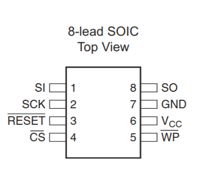
The first step is to remove the chip from the PCB (desoldering works well for this task). Next, we need to add wires to the chip’s pins according to the datasheet and then connect them to the Raspberry Pi. Fortunately, someone has already created a helpful diagram (splasher - Pinout) to guide you through the wiring. Keep in mind that you may need to adjust the connections based on the specifics of your chip’s datasheet.

3. Script preparation
The Raspberry Pi provides extensive control over its GPIO pins. For simplicity, I will use the Python library RPi.GPIO, which offers all the functionality we need to create a script for reading data from the chip.
The first step is to understand the control flow that we need to implement. To verify the wiring, I typically start by reading the device ID and manufacturer ID. The datasheet referenced earlier outlines the serial protocol for reading the manufacturer ID.

The following code snippet shows the basic structure of the script, along with the operations we need to implement before interacting with the chip. (Note: the snippet requires JavaScript to be enabled to view properly)
For detailed implementation of each operation, you can refer to the full script, as the specifics will not be covered here. If everything is set up correctly, including the wiring, the output should look something like this:
root@raspberrypi:~ # python3 spi_read_deviceid.py
Manufacturer-ID     : 31 (0b11111)
Device-ID
  - Family Code     : 1 (0b1)
  - Density Code    : 7 (0b111)
  - Sub Code        : 0 (0b0)
  - Product Variant : 1 (0b1)
EDI                 : 1 (0b1)
4. Reading the flash
The time required to extract data from the flash chip can vary depending on its size. For larger chips, the extraction process could take up to 10 minutes. The Python approach described here is quite basic and doesn’t prioritize performance. There are many resources available online that can help you read the contents of a flash chip much faster. The script provided was created for educational purposes and is not optimized for speed.
When you run the modified script to read the first 1024 bytes of the flash, it will generate a file named dump.spi.bin in the same directory.
root@raspberrypi:~ # sudo python3 spi_read_flash.py
-- snipped --

Reading flash... ━━━━━━━━━━━━━━━━━━━━━━━━━━━━━━━━━━━━━━━━   1% 0:22:56
If we examine this file, it should contain random bytes. However, if the file is filled entirely with FF values, this indicates an issue — most likely that you forgot to apply the clock signal.
00000000: 0055 aa01 1000 0000 00a8 0a00 0000 8f41  .U.............A
00000010: 2510 2002 0080 2302 2201 01c6 7cff 0722  %. ...#."...|.."
00000020: 2201 01b6 0000 0040 8009 2002 2200 01b6  "......@.. ."...
00000030: e5ff 1f22 42c6 18b6 3500 0002 0000 0002  ..."B...5.......
00000040: 22e1 2007 2200 01b6 0c00 0002 22df 2007  ". .".......". .
00000050: 2200 01b6 22e5 2007 2200 01b6 0c00 0002  "...". .".......
00000060: 0500 2403 6209 20ac 0000 0000 0000 0000  ..$.b. .........
00000070: 0000 0000 0000 0000 0000 0000 0000 0000  ................
00000080: 0000 0000 0000 0000 0000 0000 8000 69fc  ..............i.
00000090: 0000 0000 0000 0000 0000 0000 0000 0000  ................
000000a0: 0000 0000 0000 0000 0000 0000 0000 0000  ................
000000b0: 0000 0000 0000 0000 0000 0000 0000 0000  ................
000000c0: 0000 0000 0000 0000 0000 0000 0000 0000  ................
A quick analysis of the flash dump revealed the web server’s files, along with the compressed core of the firmware (as described in fsapi-tools - Firmware Analysis). Additionally, all known Wi-Fi credentials are stored in plain text within the file.