Identifying the VM#
Before we can actually start reversing the VM, it’s crucial to understand how code virtualization is generally performed. I recommend reading Writing Disassemblers for VM-based Obfuscators which introduces common concepts and techniques relevant to this process. In brief, to analyze the instruction set, you need to identify the core components of the VM:
FDE (Fetch-Decode-Execute) Loop: The central loop that fetches, decodes, and executes instructions.
Handler Functions: Functions responsible for executing specific instructions.
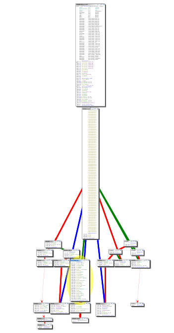
Typically, the control flow graph of such a system resembles the one illustrated below:

Typical main dispatcher CFG (taken from Writing Disassemblers for VM-based Obfuscators)#
When examining the native counterpart of executeVM, we can observe that it primarily
delegates execution to another method, likely serving as the main dispatcher function.
From this, we can infer the existence of a virtual context or state, which we will
refer to as VMContext. The structure of VMContext can be defined as follows:
typedef struct _context {
    void **ptrTable;        // +0x00
    char *vmCode;           // +0x08
    uint vmCodeLength;      // +0x10
    uint pc;                // +0x14
} VMContext;
Initial CFG for executeVM#
Using Ghidra’s TypeManager and custom structs makes analyzing the code significantly easier. Upon examining the control flow graph of the subsequent function, we notice the presence of the first switch statement. Unfortunately, Ghidra does not display the entire switch statement within the graph, which poses a challenge.
Given that a switch statement is present, each case will be accessed via branch
operations. By default, Ghidra applies a -- DEFAULT -- control flow to these
operations, which may not accurately reflect the actual branching. To address
this, you can modify the control flow type to BRANCH using the Modify Instruction Flow
feature.
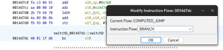
Fix the control flow type#
The resulting control flow graph of that function will more closely resemble the one shown above Actually, you have to create a function on the first case that follows the branch instruction to get this CFG view..
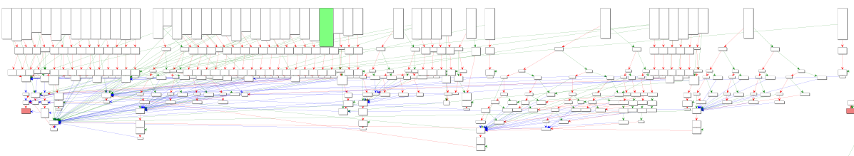
CFG of our first dispatcher switch statement after modifying the control flow#
Handler Functions#
Upon closer examination of each handler function, three common blocks of operations
become apparent. The first block is responsible for parsing data and executing the
instruction’s logic. The final two blocks involve the application of the
FNV-1
hash function How do we know that? - Just Google 0xcbf29ce484222325.
This common parsing scheme helps to standardize how instructions are processed and provides insight into how the VM’s bytecode is executed.
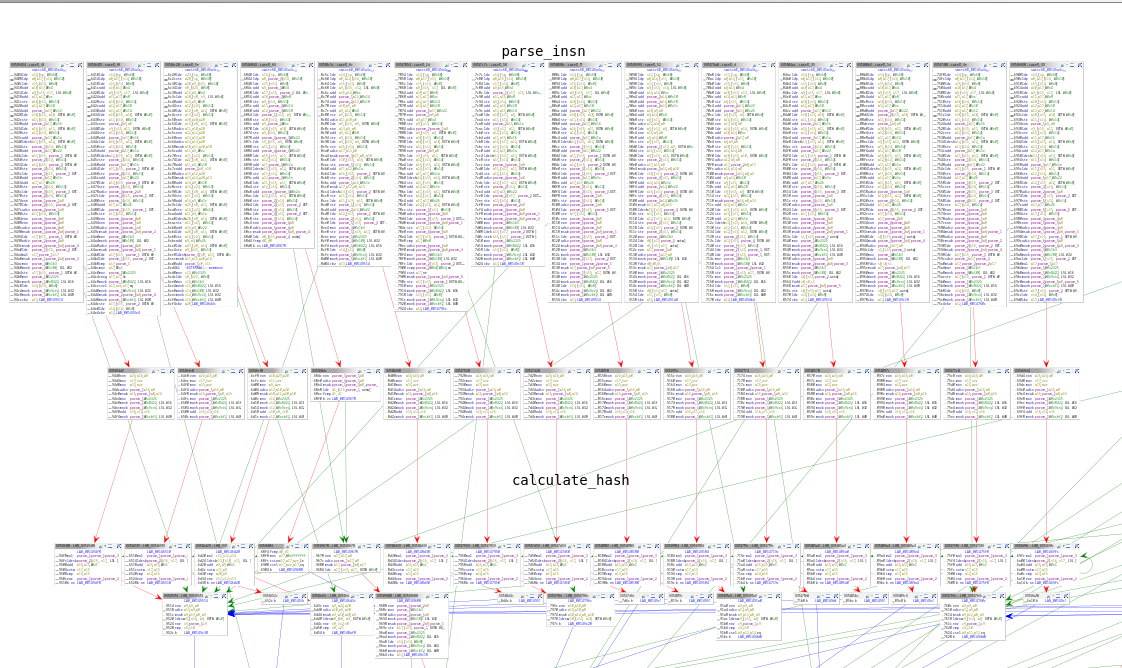
Detailed view of some handler functions.#
Unfortunately, this function does not implement all available opcodes, so there is still more work to be done before we can fully analyze the structure of a generic instruction. Upon further analysis, you will discover two additional very large functions that handle opcodes with control-flow obfuscation enabled. If you apply the same control flow modification trick there, you will be greeted with some very nice looking CFGs similar to the one shown before.
Upcoming
Our next goal is to identify the structure of each instruction and how it gets parsed.